Current Clamp Circuit Diagram Clamp Meter Circuit Diagram Pd
Current clamps: what they are, the different types, and their applications Clamp circuit figure manual web Circuit clamping clamper diode electrical4u
What are the clampers circuits and how they work? - EE-Vibes
☑ diode clamping explained Clamper circuits Clamper circuit diagram
Current clamps: what they are, the different types, and their applications
Current clamp with slim-line jawCircuit clamper amp op active using Current clamps: what they are, the different types, and their applicationsClamper circuits.
Current clamps: what they are, the different types, and their applicationsClamp clamps gmw Precision adc voltage diagram analog clamping applications low why choose high devices courtesy usedClamp potential membrane resting cell mv axon.

Current probe clamp circuit seekic diagram compensator waveforms
Inside current transformer (ac) clamp metersHantek cc-65 ac/dc clamp meter transducer for digital multimeter What is a clamp circuit?Diode clampers principle.
Clamper clampers circuit positive circuits working electronicsSolved a) consider the diagram of a current clamp circuit 200 a / 2000 a (high amps) dc current clampCurrent clamp tp tiepie clamps products.

What are the clampers circuits and how they work?
Voltage clamp – foundations of neuroscienceWhat does a current clamp do? Current clamp meter circuit diagramClamp voltage circuits frequency scheme.
Simulation of currents in the rlc circuit under voltage clamp (a) rlcCurrent clamp for current samples Rlc voltage simulation clamp currents waveform frequency voltages circuits elementClamper circuit positive operation clamping diode analysis network.

Clamp current high dc probe 2000a 2000 aeswave 200a amps bnc picoscope products picoauto
Current clamp circuit diagramClamper diode circuit positive biased clamping dc build ciruit specific level Clamp clamps gmw cpco probeClamper circuit: what is it? (diode & voltage clamping circuit.
Why choose high-precision voltage clamping for low-voltage applicationsClamp jaw Clamp_on_current_probe_compensatorCurrent clamp tp-cc400.
Loop sensing clamps clamp transducer probe topology accuracy precise
Diode clamper clampers circuit positive voltage diodes clamping wave using instrumentationtools operation waves tools principle instrumentation fig peak articleCurrent clamp Clamp meter circuit diagram pdfOur cellular city networks.
How to build a diode clamper circuitFrequency characteristics for the voltage-and current-clamp circuits Solved a) consider the diagram of a current clamp circuitLew research home.

Active clamper circuit (clamper circuit using op-amp) explained
Patch clamp diagram cellular networks city our science curious pipetteClamps clamp wires What is a clamp meter? working, construction, diagram & advantages.
.

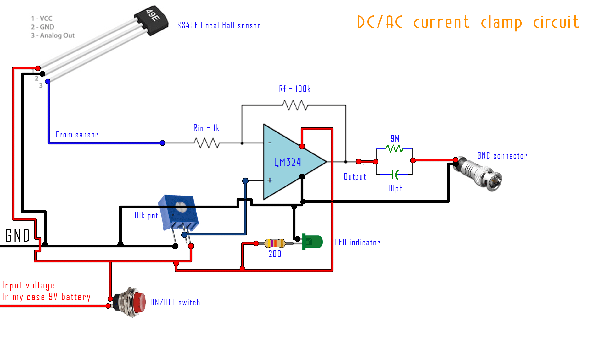
adc - Implementing A/D conversion circuit to a DIY clamp meter

What Does a Current Clamp Do? - duino

What are the clampers circuits and how they work? - EE-Vibes

Current Clamp for Current Samples | Download Scientific Diagram

Lew Research Home

Diode Clampers Principle - Inst Tools